Inspection
When inspecting a steel wire rope, special attention should be paid to the sections that, as experience shows, are most exposed to wear and damage.
Wear, broken wires, deformations, and corrosion are visible signs that the rope is not in good technical condition.
Wear of a steel wire rope is a natural phenomenon, which can be reduced by selecting the appropriate rope construction and using proper equipment. Regular and correct lubrication reduces both external and internal wear.
Broken wires usually appear in the final stage of the rope’s service life and result from material fatigue and bending wear. Breaks in specific locations may also indicate mechanical failure of the equipment. Proper lubrication reduces internal friction, thus lowering the risk of material fatigue.
If the number of broken wires is small, the rope can be repaired by reattaching it.
 Attention!
A steel wire rope must not be cut without proper preparation. Bend it in such a way that the break reaches deep into the rope’s structure, preventing any loose ends from remaining.
Rope deformations are usually the result of mechanical damage. In the case of severe deformation, the rope’s strength is significantly reduced.
Corrosion, both external and internal, is a sign of improper lubrication. Localised rust spots on the outer wires can quickly lead to wire breakage. Internal corrosion may occur in certain working environments and results from using too little or an unsuitable lubricant. This defect can be recognised, among other signs, by a reduction in rope diameter, although the most reliable method is internal inspection.

Steel wire rope discard criteria
Steel wire ropes should be withdrawn from service in accordance with applicable industry standards or the manufacturer’s recommendations.
The decision to remove a rope from service should be made only by competent personnel with appropriate knowledge of current standards, regulations, and operating conditions.
WARNING! Improper inspection of the technical condition or incorrect disposal of a steel wire rope can lead to serious injury or accidents.
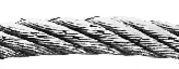
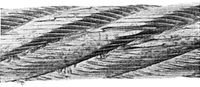
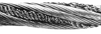
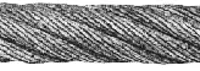
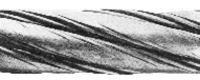
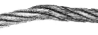
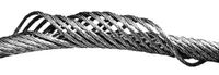
Typical examples of steel wire rope damage and wear
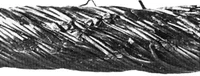
Mechanical damage caused by wire movement over sharp edges under load.
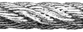
Localised wear caused by contact with steel structures.
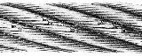
Wire vibration between the drum and the sheave.
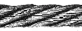
Narrow, worn area along the wire causing wire breakage, resulting from an oversized sheave groove or the wire running over small deflector rollers.
Wire breaks in the form of two parallel lines indicate that the wire is running in a sheave with a groove that is too narrow.
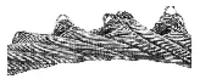
Severe wear combined with high pressure on the tread.
The fibre core is squeezed out.
Excessive wear of the longitudinal steel wire rope caused by wear at the crossover points on a multi-layer wire rope drum.
Severe rusting caused by the wire running through chemically treated water.
Excessive wear of the longitudinal steel wire rope caused by wear at the crossover points on a multi-layer wire rope drum.
Severe corrosion caused by the wire running through chemically treated water.

Exposed steel core due to support loading.
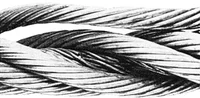
Fracture of the steel core caused by heavy impacts.
Refer to the instructions regarding breaks in the outer strands.
Core deformation caused by twisting effects resulting from operation in low temperatures (impact loading).
Typical example of localised wear and indentations caused by kinking.
Rotation-resistant steel wire rope with forced strand sections caused by uneven twisting forces.
Typical damage occurring after termination on a multi-part crane rope.
Discard criteria for single-layer or parallel-closed ropes (according to ISO 4309:2010)
for damaged (broken) wires over a length of 6d and 30d
| Rope Category Number (RCN) | Total number of load-bearing wires in the outermost layer of the rope part (a) – n | Number of visible broken outer wires (b) | |||||
| Rope sections running in steel sheaves and/or wound on a single-layer drum (randomly distributed wire breaks) | Rope sections wound on a multi-layer drum (c) | ||||||
| Class M1 to M4 or unknown class (d) | All classes | ||||||
| Cross-pitting | Longitudinal pitting | Combined transverse and longitudinal pitting | |||||
| Over the length 6d(s) | Over the length 30d(s) |
Over the length 6d(s) | Over the length 30d(s) |
Over the length 6d(s) | Over the length 30d(s) |
||
| 1 | n ≤ 50 | 2 | 4 | 1 | 2 | 4 | 8 |
| 2 | 51 ≤ n ≤ 75 | 3 | 6 | 2 | 3 | 6 | 12 |
| 3 | 76 ≤ n ≤ 100 | 4 | 8 | 2 | 4 | 8 | 16 |
| 4 | 101 ≤ n ≤ 120 | 5 | 10 | 2 | 5 | 10 | 20 |
| 5 | 121 ≤ n ≤ 140 | 6 | 11 | 3 | 6 | 12 | 22 |
| 6 | 141 ≤ n ≤ 160 | 6 | 13 | 3 | 6 | 12 | 26 |
| 7 | 161 ≤ n ≤ 180 | 7 | 14 | 4 | 7 | 14 | 28 |
| 8 | 181 ≤ n ≤ 200 | 8 | 16 | 4 | 8 | 16 | 32 |
| 9 | 201 ≤ n ≤ 220 | 9 | 18 | 4 | 9 | 18 | 36 |
| 10 | 221 ≤ n ≤ 240 | 10 | 19 | 5 | 10 | 20 | 38 |
| 11 | 241 ≤ n ≤ 260 | 10 | 21 | 5 | 10 | 20 | 42 |
| 12 | 261 ≤ n ≤ 280 | 11 | 22 | 6 | 11 | 22 | 44 |
| 13 | 281 ≤ n ≤ 300 | 12 | 24 | 6 | 12 | 24 | 48 |
| n > 300 | 0,04 x N | 0,08 x N | 0,02 x n | 0,04 x N | 0,08 x N | 0,16 x N | |
Note: Ropes with outer strands in Seale construction, in which the number of wires in each strand is 19 or fewer (e.g. 6x19 Seale), are listed in this table two rows higher than the construction in which they would normally be classified based on the number of load-bearing wires in the outer strand layer.
Explanations:
(a) In this International Standard, filler wires are not considered load-bearing wires and are not included in the value n.
(b) One broken wire has two ends (counted as one wire).
(c) The given values apply to damage occurring in the crossover and interference zones caused by the rope’s fleet angle — they do not apply to rope sections working solely in sheaves without winding onto a drum.
(d) Doubling the permissible number of broken wires may be applied for ropes operating in mechanisms with a duty classification of M5 to M8.
(e) d = nominal rope diameter.
Discard criteria for low rotation or rotation-resistant ropes (according to ISO 4309:2010)
for broken wires over a length of 6d and 30d.
| Rope Category Number (RCN) | Total number of load-bearing wires in the outer layer of the rope section (a) – n | Number of visible broken outer wires (b) | |||||
| Rope sections running in steel sheaves and/or wound on a single-layer drum (randomly distributed wire breaks) | Rope sections wound on a multi-layer drum (c) | ||||||
| Over a length of 6d (d) | Over a length of 30d (d) |
Over a length of 6d (d) | Over a length of 30d (d) |
||||
| 21 | 4 rope parts – n ≤ 100 | 2 | 4 | 2 | 4 | ||
| 22 | 3 or 4 rope sections – n ≤ 100 | 2 | 4 | 4 | 8 | ||
| At least 11 outer strand sections | |||||||
| 23-1 | 71 ≤ n ≤ 100 | 2 | 4 | 4 | 8 | ||
| 23-2 | 101 ≤ n ≤ 120 | 3 | 5 | 5 | 10 | ||
| 23-3 | 121 ≤ n ≤ 140 | 3 | 5 | 6 | 11 | ||
| 24 | 141 ≤ n ≤ 160 | 3 | 6 | 6 | 13 | ||
| 25 | 161 ≤ n ≤ 180 | 4 | 7 | 7 | 14 | ||
| 26 | 181 ≤ n ≤ 200 | 4 | 8 | 8 | 16 | ||
| 27 | 201 ≤ n ≤ 220 | 4 | 9 | 9 | 18 | ||
| 28 | 221 ≤ n ≤ 240 | 5 | 10 | 10 | 19 | ||
| 29 | 241 ≤ n ≤ 260 | 5 | 10 | 10 | 21 | ||
| 30 | 261 ≤ n ≤ 280 | 6 | 11 | 11 | 22 | ||
| 31 | 281 ≤ n ≤ 300 | 6 | 12 | 12 | 24 | ||
| n > 300 | 6 | 12 | 12 | 24 | |||
Note: Rotation-resistant ropes with outer strands in Seale construction, in which the number of wires in each strand is 19 or fewer (e.g. 18x9 Seale – WSC), should be classified in the table two rows higher than indicated by the number of load-bearing wires in the outer strand layer.
Explanations:
(a) In this International Standard, filler wires are not considered load-bearing and are not included in the value n.
(b) One broken wire has two ends but is counted as one damaged wire.
(c) The given values apply to deterioration occurring in crossover or interference zones resulting from the rope’s fleet angle. They do not apply to sections running solely through sheaves without being wound onto a drum.
(d) d = nominal diameter of the steel wire rope.